Balancing robot board bring-up
Finished 2026
The board never ran firmware. The schematic, the layout that got built and the firmware drivers came from the course. What's mine is the soldering, the chassis, the debugging and the write-up.
A self-balancing robot board that never came up. I hand-soldered it, debugged it over SWD, and traced the problem to the microcontroller's 3.3 V supply, though I never confirmed the cause.
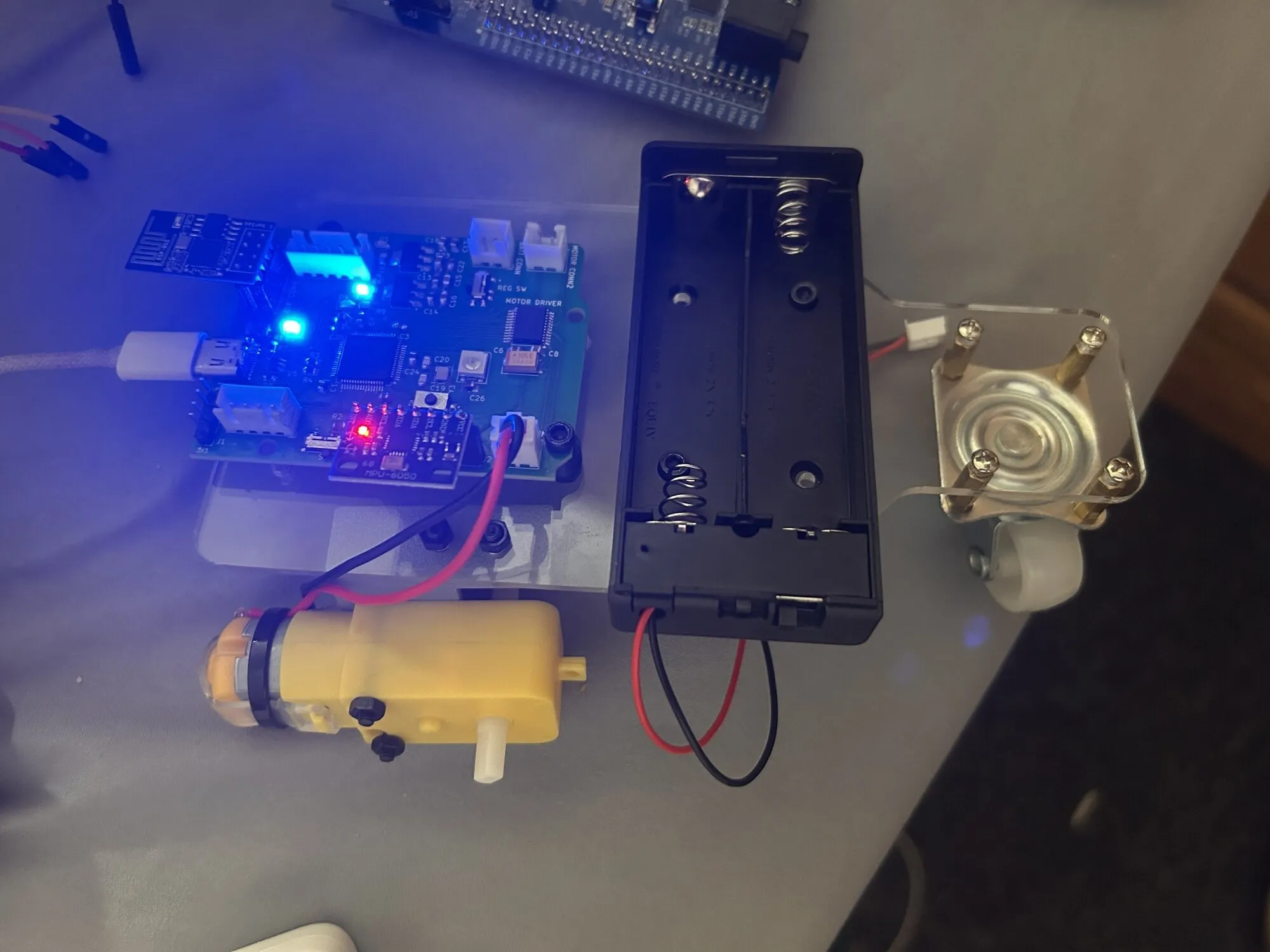
The board
The goal was a two-wheel robot that balances. The board has an STM32F401 at 84 MHz from a 16 MHz crystal, a TB6612FNG motor driver, an MPU6050 IMU on I2C, an MT6701 magnetic encoder on a second I2C bus, a WS2812 LED driven by a timer and DMA, and an ESP-01 for a Wi-Fi control page. It’s two layers and about 68.65 by 53.48 mm.
What was mine
I hand-soldered the board, except the microcontroller and the USB connector, which the instructors did. I routed my own layout in KiCad from the course schematic, but the instructor’s layout was the one that got built. I drew the chassis in CAD and exported a DXF for laser cutting. The firmware scheduler, telemetry and command code in main.c is mine: the IMU runs at 100 Hz through a complementary filter (coefficient 0.995), telemetry goes out every 100 ms as $speed,roll,pitch,counter, and drive commands are single bytes. The peripheral drivers came from the instructor and the IMU driver is a third-party library.
What happened
It never ran firmware. The USB-C port never enumerated on my Linux machine, and dmesg just said device descriptor read/64, error -71. USB was the only way to program the board, so I couldn’t flash it.
So I went in over SWD with the ST-Link on an STM32F4 Discovery board, jumpers pulled, wired to SWDIO, SWCLK, ground and 3.3 V. Both STM32_Programmer_CLI and st-info gave the same answer:
Voltage : 2.90V
Error: Unable to get core ID
Error: No STM32 target found!
I tried both wire orders, hot-plug and connect-under-reset, and both power sources. Same result. That rules out the programmer, the cable and my wiring. My diagnosis is that the chip was being phantom-powered through the protection diodes on its I/O pins while its real VDD net wasn’t connected. In the photo the ESP-01, a blue LED and the IMU’s red LED are lit, so some 3.3 V loads work. The suspect is the microcontroller’s own VDD connection. I never probed the regulator or the VDD pins, so the cause is still a guess, and the balancing controller stayed a plan on paper.