Arduino DSP shield with a 10-bit R-2R DAC
Finished 2026
The board layout started from an instructor's template. I added the circuit and the routing. I never measured the 10-bit DAC on the shield, only the 5-bit one on a breadboard.
A two-layer Arduino Uno shield with an IMU, an OLED, buttons, pots, audio jacks and a 10-bit R-2R DAC, routed in KiCad from an instructor's template, plus a 5-bit breadboard DAC I measured on a scope.
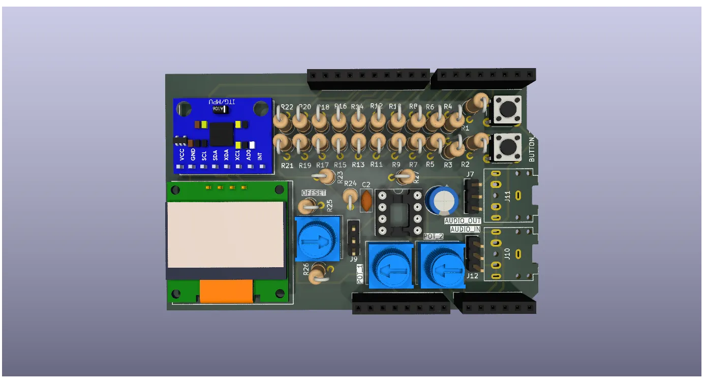
The shield
It plugs on top of an Arduino Uno and gives it a small signal-processing playground: an MPU6050 IMU and a 0.96 inch OLED on I2C, two buttons, three 100k trim pots, audio in and audio out, and a 10-bit R-2R DAC on pins D4 to D13. The IMU and the display are off-board modules on headers. The DAC feeds an MCP6002 op-amp stage with an offset pot, and the ladder is built from 10k and 20k resistors.
The DAC
I built a 5-bit version of the ladder on a breadboard first. The Arduino counts 0 to 31 on D4 to D8 every 10 ms, and a Falstad simulation of the same circuit reads 4.167 V at the test point. On the scope the output is a set of separate levels, but at 200 ms per division it’s not a clean staircase, and I never did a proper sweep.
The firmware demos
- Fan controller: there’s no real fan, and a pot stands in for temperature. Timer1 samples the ADC every 50 ms and averages 10 samples, so the reading updates about twice a second. Timer2 makes about 244 Hz PWM on pin 11. The “temperature” is a pot mapped from 0 to 50 C. Button 1 toggles the fan and button 2 cycles the sensitivity between low, medium and high.
- Solar charger: reads two analog inputs against a 2.5 V threshold and shows SOLAR or BATTERY on the OLED.
- HAL drivers: short test sketches for the ADC, PWM, HC-SR04, MPU6050 and SSD1306. They’re sketches, not a library.
What was mine
The layout began as an instructor’s template: the Arduino headers, the outline, the mounting holes and the IMU connector, with no routing. The final board has 46 footprints, 196 track segments and a ground zone. So I added the resistors, capacitors, op-amp socket, buttons, pots, audio jacks and headers, did all the routing, and wrote the silkscreen labels. The schematic started from the template’s too.