Op-amp phase shifter
Finished 2025
An op-amp circuit with a potentiometer that shifts the phase of a 500 Hz sine without changing its amplitude, worked out by hand, simulated in LTspice and measured on a scope at three pot settings.
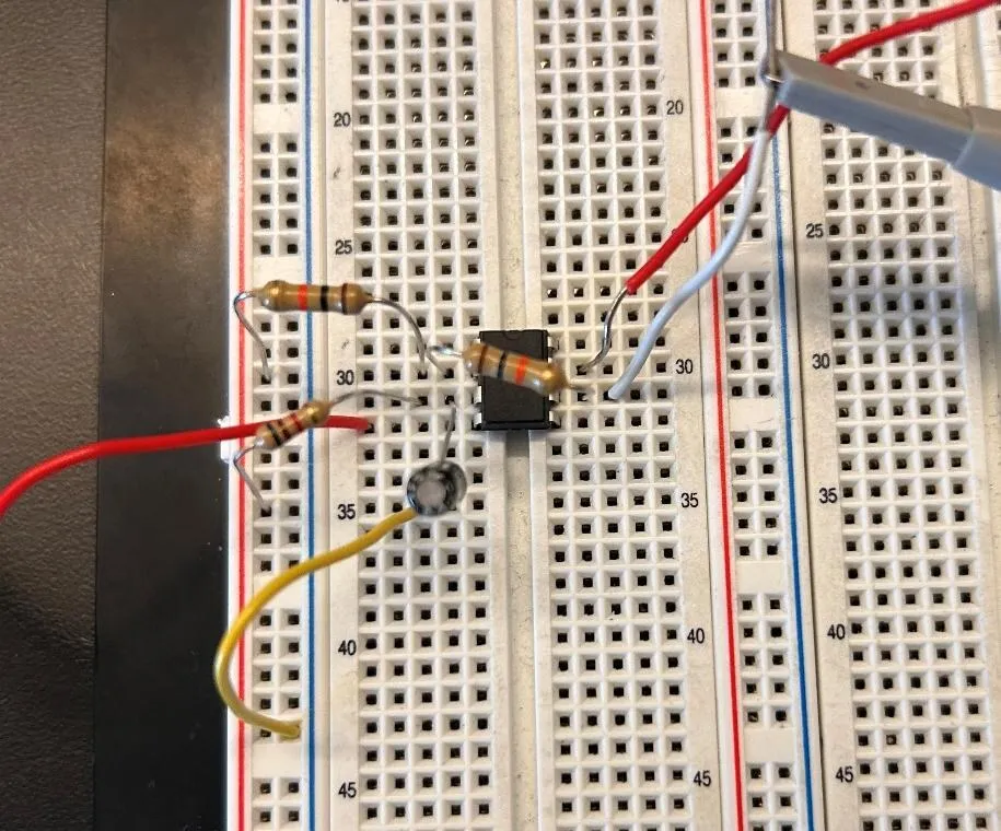
The circuit
It’s one op-amp, two 10k resistors, a 100 nF capacitor and a pot. The pot and the capacitor form an RC network on the non-inverting input, and turning the pot slides the output’s phase against the input. The amplitude doesn’t change, only the timing.
I worked the transfer function out by hand. With the two resistors equal it simplifies to (1 - sCRp) / (1 + sCRp), which is an all-pass filter: gain of one at every frequency, with a phase that depends on Rp. At 500 Hz the capacitor’s impedance is about -3.2k j ohms, which is what the pot fights against.
Calculated, simulated, measured
I picked three pot values, worked out the phase shift for each, ran each in LTspice and then built it and measured on the scope.
| Pot | Calculated | Simulated | Measured |
|---|---|---|---|
| 100 ohm | -3.6 deg | -1.97 deg | no reading |
| 5k | -114.6 deg | -115.5 deg | -110.29 deg |
| 10k | -145.0 deg | -145.0 deg | -149.85 deg |
At 100 ohms the shift is only about two degrees, so the traces sit on top of each other. The scope couldn’t find an edge to measure between them and reports “No edges”, so that row has no number. At 5k I measured -110.3 degrees against -115.5 simulated, and at 10k I measured -149.9 against -145.0. The scope read 502 Hz for the input.