RC filters, simulated and measured
Finished 2025
Low-pass, high-pass, second-order, band-pass and twin-T notch filters built from 1k and 10k resistors and 0.1 uF capacitors, each simulated in LTspice and then measured on a scope.
The setup
These are all passive RC networks, no op-amps. The low-pass and high-pass use 1k and 0.1 uF, so the corner is 1 / (2 pi RC) = 1.59 kHz. For each filter I simulated it in LTspice, built it, and measured gain and phase on the scope at the frequencies where the simulation said it should be 3, 6 and 9 dB down.
Low-pass
| Frequency | Gain, simulated | Gain, measured | Phase, simulated | Phase, measured |
|---|---|---|---|---|
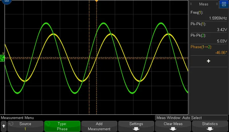
| 1.59 kHz | -3.02 dB | -3.35 dB | -45.07 deg | -46.86 deg |
| 2.78 kHz | -6.08 dB | -6.45 dB | -60.22 deg | -57.27 deg |
| 4.22 kHz | -9.05 dB | -9.11 dB | -69.34 deg | -67.88 deg |
The scope shot above is the first row: 3.42 V out of 5.03 V in is 0.68, which is -3.35 dB.
High-pass
| Frequency | Gain, simulated | Gain, measured | Phase, simulated | Phase, measured |
|---|---|---|---|---|
| 1.59 kHz | -3.00 dB | -3.06 dB | -44.97 deg | -43.38 deg |
| 912 Hz | -6.07 dB | -5.90 dB | -60.18 deg | -56.75 deg |
| 609 Hz | -9.01 dB | -8.64 dB | -69.26 deg | -66.98 deg |
I also put a 1 V DC offset on the input to check: the high-pass blocks it and the low-pass passes it.
Second-order low-pass
Two of the same RC stages in a row move the corner down to about 600 Hz. I used 0.375 / (2 pi RC), which is 596.8 Hz, and measured 602 Hz.
| Frequency | Gain, simulated | Gain, measured | Phase, simulated | Phase, measured |
|---|---|---|---|---|
| 602 Hz | -3.06 dB | -3.05 dB | -52.97 deg | -54.83 deg |
| 1.02 kHz | -6.09 dB | -6.02 dB | -73.04 deg | -73.60 deg |
| 1.51 kHz | -9.11 dB | -8.91 dB | -88.08 deg | -91.10 deg |
The measured numbers land within about 0.4 dB and 3.5 degrees of the simulation on all three filters.
Band-pass and notch
The band-pass is a high-pass stage (1k, 0.1 uF, corner 1.59 kHz) followed by a low-pass stage (10k, 0.1 uF, corner 159 Hz). The high-pass corner sits above the low-pass corner, so the pass region is narrow and low. The center is at 501 Hz in LTspice and 500.64 Hz on the scope, and it’s down about 21 dB there: 450 mV out of 5.2 V in.
The notch is a twin-T with every resistor 10k and every capacitor 0.1 uF. The null is at 158.5 Hz in LTspice and 158.47 Hz on the scope, and it’s about 12 dB deep both ways: 1.30 V out of 5.2 V in. A proper twin-T uses half the resistance and double the capacitance in the shunt leg, and mine uses equal values, which is why the null is only 12 dB deep. These stages are also unbuffered, so the band-pass loses a lot in the middle partly because the two stages load each other.